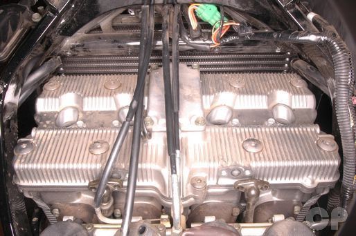
Cylinder Head Cover
SAFETY FIRST: Protective gloves and eyewear are recommended at this point.
Removal
Remove the fuel tank. See the Fuel Tank topic for more information.
Remove the spark plugs and frame cross bar. See the Spark Plugs topic for more information.
Remove the ignition coils. See the Ignition System topic for more information.
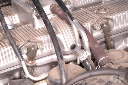
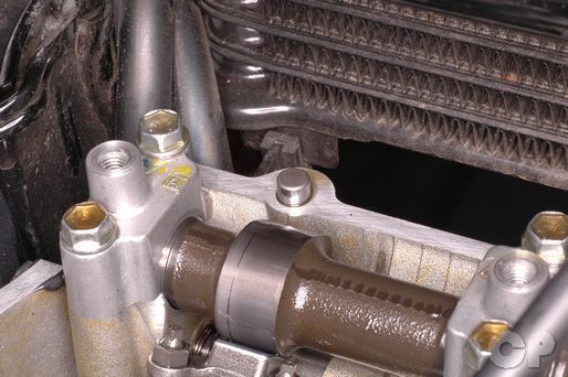
There are two oil hoses that attach to the back side of the cylinder head cover. Each oil hose has two mounting bolts.
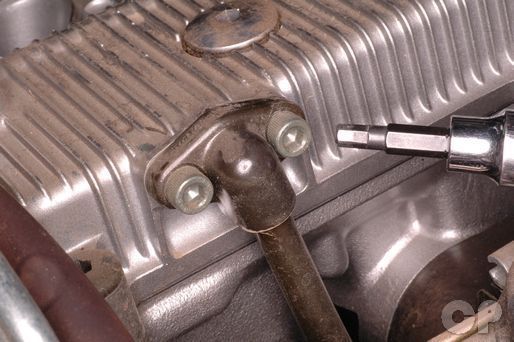


Loosen the cylinder head cover oil hose mounting bolts with a 5 mm Allen.


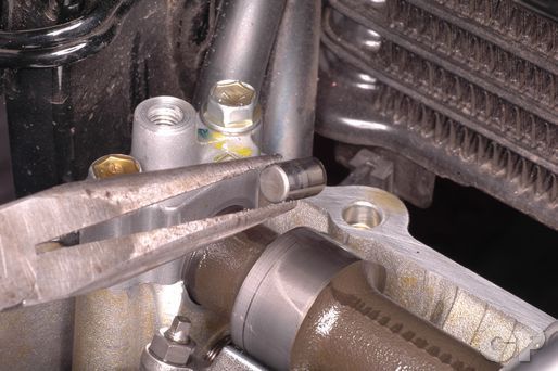
Free the oil hoses from the cylinder head cover and remove the O-rings.
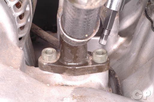


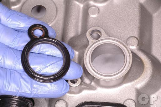
To remove the oil hose joint from the crankcase remove the two bolts with a 5 mm Allen. Remove the oil hose joint from the crankcase and discard the O-ring.
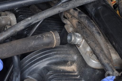
Remove the breather hose from the cylinder head cover.


Loosen the eight cylinder head cover bolts with a 6 mm Allen. Remove the bolts and their seals.


Remove the two middle cylinder head cover bolts with a 6 mm Allen.


Loosen the four cylinder head cover union bolts with a 10 mm socket. Remove the bolts and their sealing washers.


Slide off the rubber clutch cable adjuster cover.
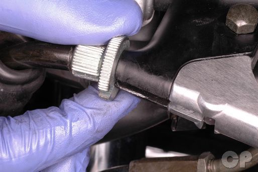


Loosen the knurled locknut and turn the adjuster in as far as it will go while aligning the slot in the adjuster and lock nut with the slot in the clutch lever perch. Pull in the clutch lever with one hand while pulling on the clutch cable with the other. Quickly release the lever and pull the cable out of the adjuster and remove it from the lever.


Guide the clutch cable down through the frame and past the carburetors.
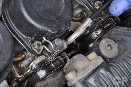


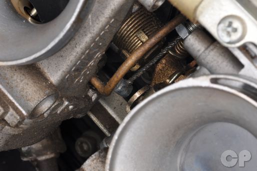
Free the choke cable from the slide on the carburetors.
Note: The carburetors on the 1988 - 1989 Katana 600 are different from the others model. They early 600 carburetors do not have a cable actuated choke, but a plunger knob on the right side.
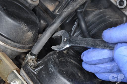


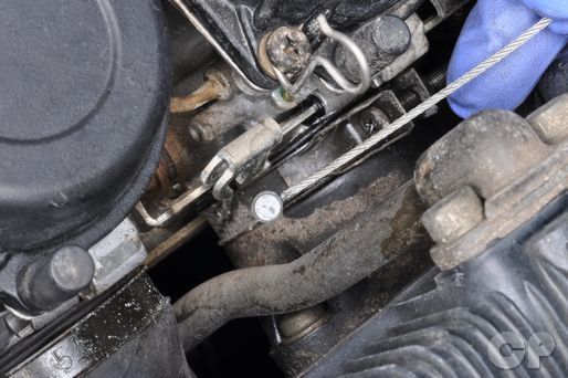
Loosen the throttle cable locknut with a 10 mm wrench. Free the throttle cable from the bracket and the throttle drum between the carburetors.


Hold the throttle cable to the side and remove the cylinder head cover.
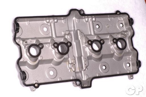


Remove the cylinder head cover and spark plug seals. Inspect the seals and replace as needed.
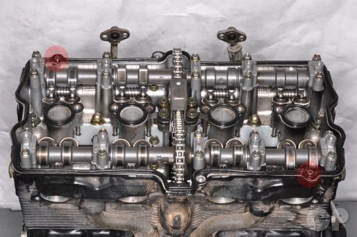
There are two dowel pins in the cylinder head.
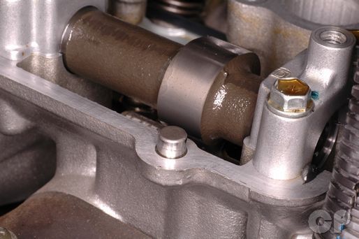
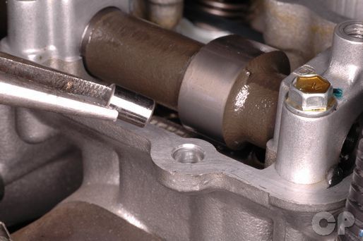
Carefully remove the dowel pins.
Installation
Install the dowel pins into the cylinder head if they were removed.

Apply Suzuki Bond 1207B or an equivalent silicone sealant to the rubber seal grove in the cylinder head cover.
Also, coat the round camshaft end cap cavities seal in sealant.
Install the cylinder head cover. Make sure the rubber seal fits properly around the cylinder head and the camshaft end caps fit into their spaces.

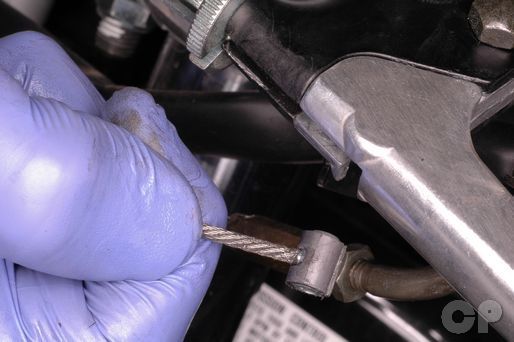
Connect the end of the throttle cable to the throttle drum between the middle carburetors. Secure the throttle cable in the bracket. Set the throttle free play to specification. Tighten the locknut with a 10 mm wrench.

Fit the choke cable to its slide.


Route the clutch cable over the engine, through the frame, between the front forks, and up to its lever.

Insert the end of the clutch cable into the lever and guide the cable through the slot in the perch, locknut and adjuster. Pull the clutch cable in and pop the cable housing into the adjuster.
Adjust the clutch cable free play. See the Clutch Cable Free Play topic for more information.
Coat the cylinder head union bolts and washers with fresh engine oil before installing them. Install the four cylinder head union bolts and new sealing washers. Torque the bolts to specification with a 10 mm socket.
Install the two center cylinder head cover bolts. Tighten the bolts to specification with a 6 mm Allen.
Install the eight cylinder head cover bolts and new seals. Torque the bolts to specification with a 6 mm Allen.
| ITEM | N-m | lb-ft |
| Cylinder head cover bolt and union bolt (600) | 13 - 15 | 9.5 - 11.0 |
| Cylinder head cover bolt (750) | 13 - 15 | 9.5 - 11.0 |
| Cylinder head cover union bolt (750) | 15 - 17 | 11.0 - 12.5 |
Connect the breather hose to the cylinder head cover.
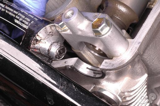
Install the oil hose joint and new O-ring to the crankcase. Insert the two bolts and tighten them to specification with a 5 mm Allen.
(Crankcase Oil Hose Joint Bolt Torque: 10 N-m or 7 lb-ft)
Install the two oil hoses and new O-rings to the back of the cylinder head cover. Tighten the bolts to specification with a 5 mm Allen.
(Cylinder Head Cover Oil Hose Bolt Torque: 10 N-m or 7 lb-ft)
Install the spark plugs and frame cross bar. See the Spark Plugs topic for more information.
Install the ignition coils. See the Ignition System topic for more information.
Install the fuel tank. See the Fuel Tank topic for more information.
Copyright 2025 - Cyclepedia Press LLC

Note: If you are viewing this document offline be sure to visit the latest version online at http://www.cyclepedia.com before attempting any repairs. Updates are made without notice.